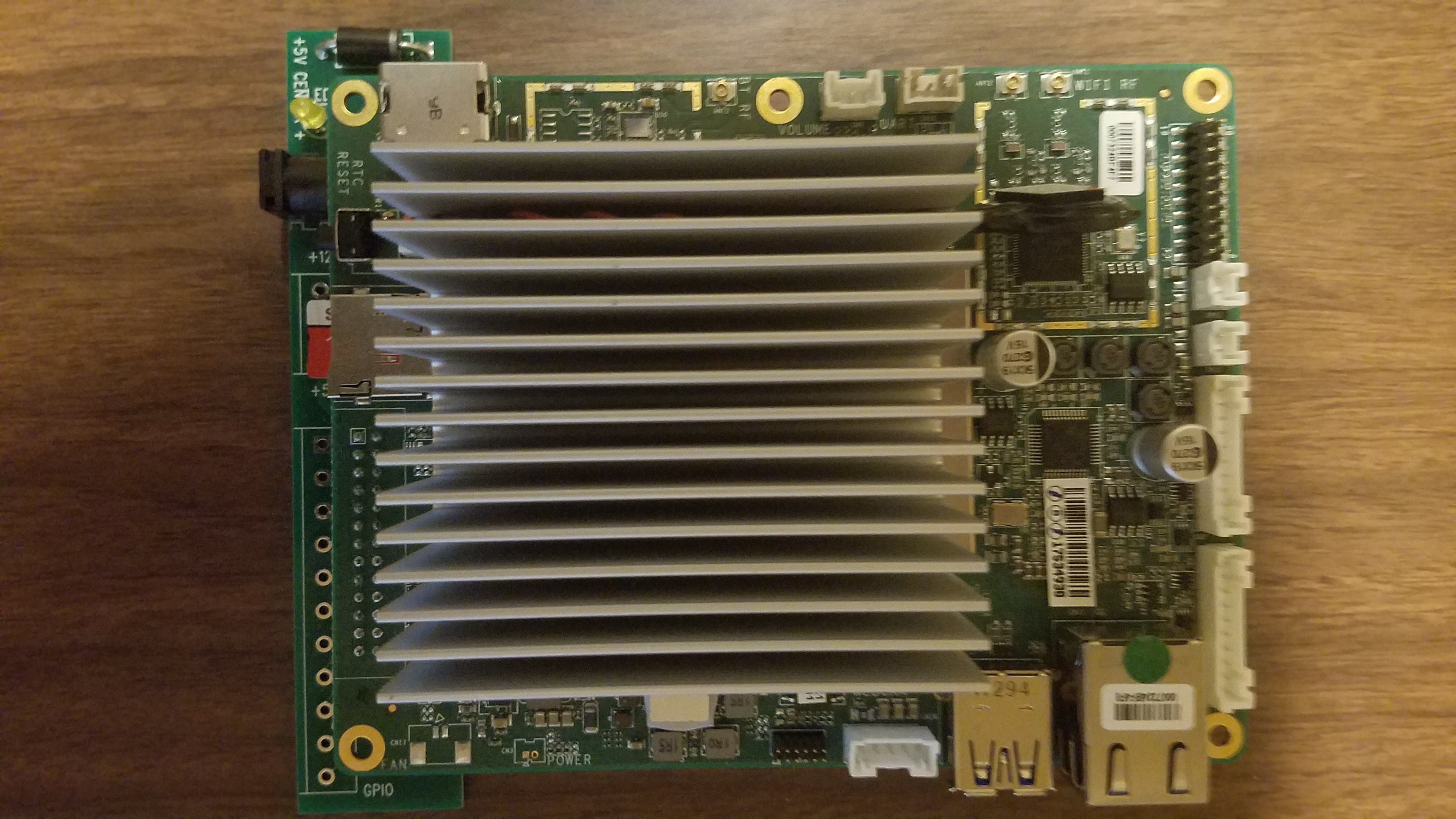
So I found some more info on the APi BIOS. According to section 2 of the reference manual which I will include at the bottom of ths post,
UEFI BIOS description
The Atomic Pi ships with AMI UEFI BIOS firmware.
The UEFI provides interactive user services, allows to perform low-level configuration, scans for boot targets and
initiates further boot.
Note that the UEFI doesn’t support legacy BIOS (MBR) booting, so your boot media must have a proper bootable
EFI partition. No further constraints are placed on the EFI partition, in particular, no signature checking is configured.
I will still get into the BIOS sometime this weekend, and check what version I have, as I am told that there are 2, v1.1, and v1.2 respectively. I will look for anything that may help with this, but I think at this point, we may have to create the EFI bootable partition mentioned above to make this work for installation images. As promised, here is the complete user reference I got with my Atomic Pi (Sorry, no pdf’s accepted here, so I’m just giving the text):
DLI Atomic Pi user guide
20190222T195046ZCONTENTS
1
Contents
1 Overview 2
2 UEFI BIOS description 3
3 GPIO pin reference 4
4 BNO055 sensor reference 7
5 Custom bus configuration reference 8
6 Technical support 9
7 Open source code 10
DLI Atomic Pi user guide: 20190222T195046Z2
1
CONTENTS
Overview
Congratulations on selecting Atomic Pi, an performant embedded controller with peripherals.
Atomic Pi has the following interfaces:
• HDMI for video and sound output;
• Additional XMOS Mayfield audio output;
• 3 user-accessible UART ports;
• USB 3.0 for connecting peripherals;
• microSD for storage (in addition to on-board eMMC);
• Ethernet, WiFi and Bluetooth connectivity options;
• 6 user-configurable GPIOs, with built-in support for running I2C or SPI bus masters over them.
The unit ships with a Bosch BNO055 absolute orientation sensor, connected via an internal I2C bus.
The firmware is based on open-source code which is provided to give you the option to build totally custom firmware.
Please contact technical support in case of any problems.
DLI Atomic Pi user guide: 20190222T195046Z2 UEFI BIOS description
2
3
UEFI BIOS description
The Atomic Pi ships with AMI UEFI BIOS firmware.
The UEFI provides interactive user services, allows to perform low-level configuration, scans for boot targets and
initiates further boot.
Note that the UEFI doesn’t support legacy BIOS (MBR) booting, so your boot media must have a proper bootable
EFI partition. No further constraints are placed on the EFI partition, in particular, no signature checking is configured.
2.1
2.1.1
Known UEFI BIOS issues
RTC date/time cannot be set via UEFI
When a date/time component is changed, the UEFI displays an error message and hangs. The component change
is applied before the hang.
The error message says:
ERROR: Class:3000000; Subclass:50000; Operation: E
(this corresponds to software error in DXE driver).
The system then hangs, requiring a power cycle.
No workaround is available; however, the RTC time can be changed on a running system, e.g. via the hwclock
utility on Linux systems. No solution is available at the moment.
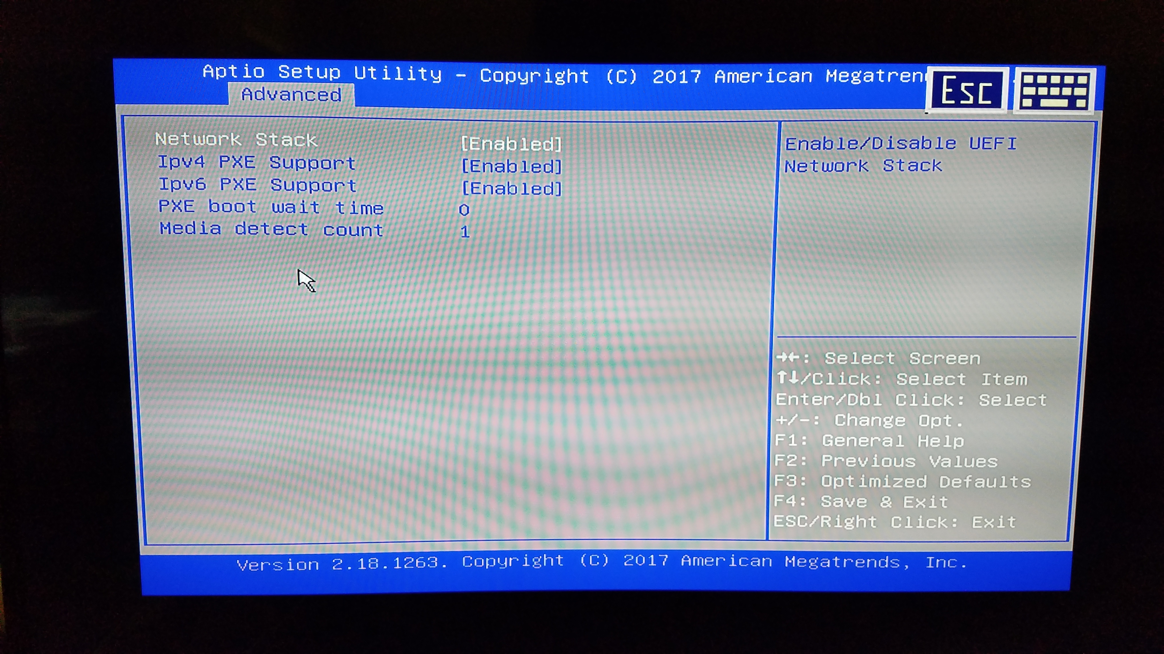
2.1.2
UEFI defaults to PXE boot
PXE is an option for booting devices from a central server over network.
The default boot target list gives network PXE boot targets priority over other boot targets, including the eMMC. If
the wired interface is active but has no PXE server, it takes some time for the UEFI to realize it needs to try other
boot options.
After a settings reset, the system is configured so that it may boot unacceptably slow (apparently not doing anything)
if connected to a network. If the network has a PXE server but it’s not intended to boot from it, unexpected operation
can occur.
No solution or workaround is available at the moment but systems not connected to wired networks are not affected.
2.1.3
UEFI boot target anomalies
The UEFI keeps a priority list of targets to boot. It rescans available devices and interfaces (eMMC, SD, USB) on
boot and adds bootable devices to its list.
The UEFI seems to attempt to boot the previously successful boot target before rescanning the list, possibly failing
boot if it doesn’t find it.
If you e.g. install a bootable image from USB to eMMC, and expect that the next boot will be performed from eMMC,
the USB device may be booted instead, or the boot may fail if the device is detached. Subsequent boots are not
affected.
A possible workaround is to perform an additional power cycle several seconds after attempting to boot from a new
installation. No solution is available at the moment.
Additionally, the boot target counter doesn’t seem to reset by itself; the possible targets seem to accumulate as well.
No impact observed so far but it’s conjectured that some internal counter may overflow if booting from extremely
(e.g. 64k) many different bootable media (at least without performing a full settings reset).
A possible workaround is to perform a full settings reset from time to time if you need to boot that many media. No
solution is available at the moment, but no actual overflow has been demonstrated so far.
DLI Atomic Pi user guide: 20190222T195046Z4
CONTENTS
3
GPIO pin reference
The Atomic Pi has 6 GPIO pins available to users, and additional lines connected to the BNO055 sensor. Here’s a
overview of them.
3.1
Addressing
In order to use GPIO pins from Linux, it’s important to understand how they are addressed in various situations.
Each GPIO has a global number in the integer GPIO namespace used with the legacy GPIO interface (e.g. through
sysfs ). This is considered a legacy interface but there are currently no plans to remove it. However, in addition
to that, recent Linux kernels expose GPIO chips, which are basically named sets of GPIOs of the same hardware
origin with a single base number; GPIOs are numbered sequentially within a chip, but the global GPIO namespace
itself needn’t be contiguous.
3.2
Pin description
Generally available pins:
Schematic name GPIO chip id Chip pin number Global pin number
Connected devices
ISH_GPIO_0 gpiochip3 21 335 ISH_GPIO_1 gpiochip3 18 332 LED Green (active low)
ISH_GPIO_2 gpiochip3 24 338 LED Yellow (active low)
ISH_GPIO_3 gpiochip3 15 329 ISH_GPIO_4 gpiochip3 22 336 ISH_GPIO_7 gpiochip3 16 330
These signals are available on the Atomic Pi’s 26-pin connector. If you have the Enchilada breakout board, the
signals are available as on it as well. Connector pin numbers are as follows:
Schematic name 26-pin connector number Enchilada connector number
ISH_GPIO_0
ISH_GPIO_1
ISH_GPIO_2
ISH_GPIO_3
ISH_GPIO_4
ISH_GPIO_7 24
25
26
18
19
20 9
10
11
3
4
5
“Volume control button” pins (available on the “VOLUME”/“VOL” connectors, can be used as regular GPIO pins):
Schematic name GPIO chip id Chip pin number Global pin number Description
GPIO_DFX_2 gpiochip1 7 348 Volume up pin
GPIO_DFX_4 gpiochip1 5 346 Volume down pin
Other pins (not on the 26-pin connector or the Enchilada connector):
DLI Atomic Pi user guide: 20190222T195046Z3 GPIO pin reference
5
Schematic name GPIO chip id Chip pin number Global pin number Connected devices
I2C2_3P3_SDA gpiochip0 62 476 BNO055 I2C SDA
I2C2_3P3_SCL gpiochip0 66 480 BNO055 I2C SCL
AU_MIC_SEL gpiochip1 0 341 XMOS_RESET gpiochip1 8 349 XMOS
Audio
mi-
crophone
loopback
selector
XMOS Audio reset (ac-
tive low)
BN_INT gpiochip1 17 358 BNO055-generated in-
terrupt (active low)
BN_RESET gpiochip1 25 366 BNO055 reset (active
low)
The XMOS_RESET line is controlled by a system service, atomicpi-hold-xmos , to bring up the XMOS Audio
device.
The AU_MIC_SEL line must be configured to logical 0 to record audio from microphone, or to logical 1 for loopback
(recording audio being played back).
Using the interrupt and reset lines is not strictly required for BNO055 operation. Additional devices may be con-
nected to its I2C bus but that would require soldering.
Note that the system core contains other GPIO pins, some connected to internal circuits. Reading the datasheet is
strongly recommended before attempting to configure them!
3.3
Using GPIOs from the shell
GPIO pin constants can be pulled in by including /usr/lib/atomicpi.sh :
. /usr/lib/atomicpi.sh
The traditional sysfs way of manipulating GPIOs from the command line is documented at:
https://www.kernel.org/doc/Documentation/gpio/sysfs.txt
It is listed as deprecated but there are no plans to remove it.
. /usr/lib/atomicpi.sh
echo $ATOMICPI_ISH_GPIO_1 >/sys/class/gpio/export
echo $ATOMICPI_ISH_GPIO_2 >/sys/class/gpio/export
echo low >/sys/class/gpio/$ATOMICPI_ISH_GPIO_1/direction
while true; do
echo low > /sys/class/gpio/$ATOMICPI_ISH_GPIO_2/direction
sleep 1
echo high > /sys/class/gpio/$ATOMICPI_ISH_GPIO_2/direction
sleep 1
done
echo $ATOMICPI_ISH_GPIO_2 >/sys/class/gpio/unexport
echo $ATOMICPI_ISH_GPIO_1 >/sys/class/gpio/unexport
Constants storing global GPIO indices are prefixed by ATOMICPI_ .
Additionally, several utilities allow GPIO control using the more modern interface (and chip id + pin index
addressing):
Constants storing " < chip id > < pin index > " are prefixed by ATOMICPICHIP_ . Due to shell expansion rules,
${ATOMICPICHIP_ISH_GPIO_0} (without quotes) will expand to two arguments, the chip id and the pin index,
which is what most of the following utilities expect.
List all GPIO chips, print their labels and number of GPIO lines:
DLI Atomic Pi user guide: 20190222T195046Z6
CONTENTS
gpiodetect
Find a GPIO line by name (the output of this command can be used as input for gpioget / gpioset ):
gpiofind
Print information about all lines of the specified GPIO chip(s) (or all chips if none are specified):
gpioinfo …
Read line value(s) from a GPIO chip:
gpioget [-l] <chip name/number> <offset 1> <offset 2> …
Options:
-l, --active-low: set the line active state to low
Set GPIO line values of a GPIO chip:
gpioset [OPTIONS] <chip name/number> = = …
Options:
-l, --active-low: set the line active state to low
-m, --mode=[exit|wait|time|signal] (defaults to ‘exit’):
tell the program what to do after setting values
-s, --sec=SEC:
specify the number of seconds to wait (only valid for --mode= ←-
,→ time)
-u, --usec=USEC: specify the number of microseconds to wait (only valid for – ←-
,→ mode=time)
-b, --background: after setting values: detach from the controlling terminal
Modes:
exit:
wait:
time:
signal:
set
set
set
set
values
values
values
values
and
and
and
and
exit immediately
wait for user to press ENTER
sleep for a specified amount of time
wait for SIGINT or SIGTERM
Wait for events on GPIO lines:
gpiomon [OPTIONS] <chip name/number> <offset 1> <offset 2> …
Options:
-l, --active-low: set the line active state to low
-n, --num-events=NUM: exit after processing NUM events
-s, --silent:
don’t print event info
-r, --rising-edge: only process rising edge events
-f, --falling-edge: only process falling edge events
-F, --format=FMT specify custom output format
Format specifiers:
%o: GPIO line offset
%e: event type (0 - falling edge, 1 rising edge)
%s: seconds part of the event timestamp
%n: nanoseconds part of the event timestamp
See /usr/lib/atomicpi.sh for details.
DLI Atomic Pi user guide: 20190222T195046Z4 BNO055 sensor reference
3.4
7
Using GPIOs from Node.JS
var atomicpi = require(“atomicpi”);
var GPIO = require(“sysfs-gpio”);
console.log(“Control by signal ID”);
GPIO.export(atomicpi.signals.ISH_GPIO_0.global_idx, (pin) => {
pin.out();
pin.high();
});
console.log(“Control with signal ID lookup on Enchilada connector first”);
GPIO.export(atomicpi.signals[atomicpi.connectors.enchilada.leds.green].global_idx ←-
,→ , (pin) => {
pin.out();
pin.low();
});
process.stdin.resume();
atomicpi.signals contains a mapping from the signal name (e.g. “ISH_GPIO_0”) to {chip,chip_ ←-
idx,global_idx} . You will need global_idx most of the time as sysfs-gpio uses the legacy sysfs
interface.
See /usr/lib/node/atomicpi.js and sysfs-gpio documentation for details.
3.5
Using GPIOs from Python
import atomicpi
import gpio as GPIO
Control by signal ID
GPIO_0=atomicpi.signals.ISH_GPIO_0.global_idx
GPIO.setup(GPIO_0, GPIO.OUT)
GPIO.output(GPIO_0, True)
Control with signal ID lookup on Enchilada connector first
GREEN_LED=atomicpi.signals[atomicpi.connectors.enchilada.leds.green].global_idx
GPIO.setup(GREEN_LED, GPIO.OUT)
GPIO.output(GREEN_LED, False)
GPIO.cleanup(GPIO_0)
GPIO.cleanup(GREEN_LED)
atomicpi.signals contains a mapping from the signal name (e.g. “ISH_GPIO_0”) to {chip,chip_ ←-
idx,global_idx} . You will need global_idx most of the time as gpio uses the legacy sysfs interface.
The gpio library largely mimics the Raspberry Pi RPIO library.
See /usr/lib/python/dist-packages/atomicpi.py and gpio documentation for details.
4
BNO055 sensor reference
The Atomic Pi has a BNO055 absolute orientation sensor attached to a custom GPIO I2C bus (configured as I2C
bus 50 by default). It combines an accelerometer, a gyroscope and a magnetometer.
You may need to calibrate the sensor to obtain desired accuracy. Consult the Bosch Sensortec reference
for details.
DLI Atomic Pi user guide: 20190222T195046Z8
4.1
CONTENTS
Using BNO055 from Node.JS
var BNO055 = require(‘bno055’);
var async = require(‘async’);
BNO055 is configured on I2C bus 50 in /etc/i2c-gpio-custom.d/bno055-bus by default var imu = new BN ←-
O055({device:"/dev/i2c-50"}); imu.beginNDOF(function() { console.info(‘imu running’); setInterval(function() {
async.series({ calibrationStatus: imu.getCalibrationStatus.bind(imu), quaternion: imu.getQuaternion.bind(imu),
euler: imu.getEuler.bind(imu), linearAcceleration: imu.getLinearAcceleration.bind(imu) }, function(err, results) {
console.info( 'imu: ', JSON.stringify(results) ); }); }, 1000); });
See bno055 package documentation for details.
4.2
Using BNO055 from Python
from Adafruit_BNO055.BNO055 import BNO055
from time import sleep
BNO055 is configured on I2C bus 50 in /etc/i2c-gpio-custom.d/bno055-bus by ←-
,→ default
sensor = BNO055(busnum=50)
assert(sensor.begin())
while True:
print(‘Euler=%0.2f:%0.2f:%0.2f Quaternion=%0.2f:%0.2f:%0.2f:%0.2f Temp=%0.2fC
,→ Mag=%0.2f:%0.2f:%0.2f Gyr=%0.2f:%0.2f:%0.2f Accel=%0.2f:%0.2f:%0.2f ←-
,→ LAccel=%0.2f:%0.2f:%0.2f Gravity=%0.2f:%0.2f:%0.2f’%(
sensor.read_euler() +
sensor.read_quaternion() +
(sensor.read_temp(),) +
sensor.read_magnetometer() +
sensor.read_gyroscope() +
sensor.read_accelerometer() +
sensor.read_linear_acceleration() +
sensor.read_gravity()
))
sleep(1)
←-
See Adafruit_BNO055 package documentation for details.
5
Custom bus configuration reference
The Atomic Pi can act as a I2C or SPI bus master on a custom set of GPIOs. This is implemented using kernel
modules i2c-gpio-custom and spi-gpio-custom (sources in /usr/src/, editable and buildable using D ←-
KMS).
The kernel modules are by default configured using systemd services i2c-gpio-custom.service and
spi-gpio-custom.service . Modules are loaded on service start and unloaded on service stop.
Services collect bus configuration items from /etc/i2c-gpio-custom.d and /etc/spi-gpio-custom.d
and set up command lines for the modules, which have form ‘bus0= < id0 > , < args… > bus1= < id1 > , < args… > …’.
Every bus needs to have a unique numeric ID (DLI default ids start with 50; it’s recommended to start custom bus
numbering with 100). GPIO pins referenced in the arguments must be specified using their global GPIO indices.
See the README files in those directories for more information.
DLI Atomic Pi user guide: 20190222T195046Z6 Technical support
6
9
Technical support
To save time, please have a look at the product FAQ page solutions. You may FAX questions to (408) 541-8459 or
email: support@digital-loggers.com .
For phone support, call (408) 330-5599 with the following so we can better serve you:
• the firmware version level installed;
• a description of the Ethernet devices connected to your unit, for example, a 10/100 PC and crossover cable,
if it’s relevant;
• a description of the WiFi or Bluetooth devices connected to your unit, i.e. their manufacturers and model
numbers, if it’s relevant.
DLI Atomic Pi user guide: 20190222T195046Z10
7
CONTENTS
Open source code
Open-source components used in the Atomic Pi are mostly unmodified, as they are in the base distribution (see
atomicpi-base-system , apt list --installed ).
Most additional components developed specifically for the Atomic Pi are provided in source form in the
firmware already. For example, avrdude support for the ATMega328PB is provided in source form as part
of /etc/avrdude.conf (it is not original).
Sources for the binary I2C and SPI custom-GPIO bus master kernel modules are provided in /usr/src in (configured
to be used by DKMS). Updated source versions will be available from Git repositories located at:
https://github.com/digitalloggers/i2c-gpio-custom.git
https://github.com/digitalloggers/spi-gpio-custom.git
Updated versions of the BNO055 sensor library for Node.JS will be available at:
https://github.com/digitalloggers/node-BNO055.git
DLI cannot provide warranty or technical support for modified units; this includes units with custom firmware.
DLI Atomic Pi user guide: 20190222T195046Z